Graphics Pipeline
Overview
The graphics pipeline transforms 3D scene data into a 2D image on screen. Modern GPUs implement this as a series of programmable and fixed-function stages operating on streams of vertices and fragments.
Pipeline Stages
High-Level Architecture
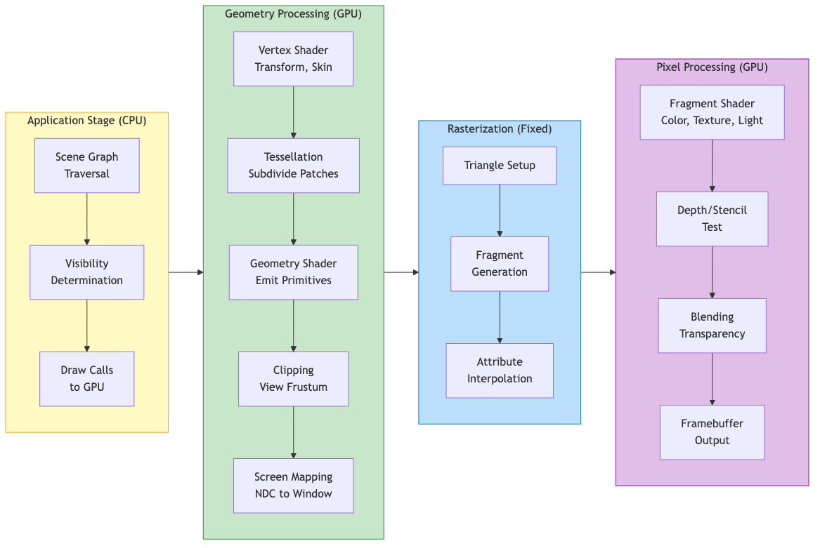
Application --> Geometry Processing --> Rasterization --> Pixel Processing --> Framebuffer
Application Stage (CPU)
- Scene graph traversal and visibility determination
- Input handling, physics, AI updates
- Issues draw calls to the GPU via graphics API
- Feeds vertex data, textures, and shader programs to the pipeline
Geometry Processing (GPU)
- Vertex Shader - Per-vertex transformations, skinning, displacement
- Tessellation (optional) - Subdivides patches into finer geometry
- Geometry Shader (optional) - Operates on whole primitives, can emit new geometry
- Clipping - Removes geometry outside the view frustum
- Screen Mapping - Maps NDC to window coordinates
Rasterization (Fixed-Function)
- Determines which pixels (fragments) a primitive covers
- Interpolates vertex attributes across the primitive using barycentric coordinates
- Generates fragment data for the next stage
Pixel Processing (GPU)
- Fragment Shader - Computes per-pixel color, applies textures and lighting
- Depth/Stencil Test - Discards occluded or masked fragments
- Blending - Combines fragment color with framebuffer (for transparency)
- Output - Writes final color to framebuffer/render target
Coordinate Systems and Transformations
Transformation Chain
Model Space --> World Space --> View Space --> Clip Space --> NDC --> Screen Space
   (M_model)     (M_view)      (M_proj)     (persp div)  (viewport)
Each transformation is represented by a 4x4 matrix applied to homogeneous coordinates.
Model (Object) Space
Local coordinate system of each mesh. The model matrix M transforms from object space to world space:
M_model = T * R * S
Where T = translation, R = rotation, S = scale. Order matters (right-to-left application).
World Space
Common coordinate system for all objects. Positions lights and cameras in the scene.
View (Camera/Eye) Space
Camera is at the origin, looking along -Z (OpenGL convention) or +Z (DirectX).
The view matrix is the inverse of the camera's world transform:
M_view = [R|t]^(-1) = [R^T | -R^T * t]
Using lookAt(eye, center, up):
f = normalize(center - eye)        // forward
r = normalize(f x up)              // right
u = r x f                          // recalculated up

        | r_x   r_y   r_z   -r.eye |
M_view =| u_x   u_y   u_z   -u.eye |
        |-f_x  -f_y  -f_z    f.eye |
        |  0     0     0       1    |
Clip Space and Projection
Projection transforms the view frustum into a canonical clip volume.
Homogeneous Coordinates
A 3D point (x, y, z) is represented as (x, y, z, w) where w != 0. The Cartesian point is recovered by dividing: (x/w, y/w, z/w).
Key properties:
- Points at infinity: w = 0 (represents directions/vectors)
- Enables translation via matrix multiplication
- Perspective division (dividing by w) produces foreshortening
| x' |   | m00 m01 m02 m03 | | x |
| y' | = | m10 m11 m12 m13 | | y |
| z' |   | m20 m21 m22 m23 | | z |
| w' |   | m30 m31 m32 m33 | | 1 |
Projection Matrices
Perspective Projection
Maps a frustum to the clip cube. After perspective division by w, produces NDC in [-1,1]^3 (OpenGL) or [-1,1]^2 x [0,1] (DirectX).
Given field of view (fov), aspect ratio (a), near (n), and far (f) planes:
t = n * tan(fov/2)          // top
b = -t                      // bottom
r = t * a                   // right
l = -r                      // left

            | 2n/(r-l)    0       (r+l)/(r-l)      0        |
M_persp =   |    0     2n/(t-b)   (t+b)/(t-b)      0        |
            |    0        0      -(f+n)/(f-n)  -2fn/(f-n)    |
            |    0        0          -1              0        |
Symmetric frustum simplification (l = -r, b = -t):
            | 1/(a*tan(fov/2))       0              0             0       |
M_persp =   |        0          1/tan(fov/2)        0             0       |
            |        0               0         -(f+n)/(f-n)  -2fn/(f-n)   |
            |        0               0             -1             0       |
After multiplication, w_clip = -z_eye, and the perspective divide produces the depth nonlinearity (more precision near the near plane).
Reverse-Z
Maps near plane to z=1 and far plane to z=0. Exploits floating-point precision distribution to reduce z-fighting at large distances. Requires a floating-point depth buffer and GL_GREATER depth test.
Orthographic Projection
No perspective foreshortening. Maps an axis-aligned box to the clip cube:
            | 2/(r-l)     0        0      -(r+l)/(r-l) |
M_ortho =   |    0     2/(t-b)     0      -(t+b)/(t-b) |
            |    0        0     -2/(f-n)   -(f+n)/(f-n) |
            |    0        0        0            1        |
Infinite Far Plane
Set f -> infinity. Useful for skyboxes and shadow maps:
M_persp_inf: replace row 3 with | 0 0 -1 -2n |
Viewport Transform
Maps NDC [-1,1]^2 to window coordinates [x, x+w] x [y, y+h]:
x_screen = (x_ndc + 1) / 2 * width + x_offset
y_screen = (y_ndc + 1) / 2 * height + y_offset
z_screen = (z_ndc + 1) / 2 * (far - near) + near     // depth range mapping
Clipping
Sutherland-Hodgman Algorithm
Clips polygons against each frustum plane sequentially. In clip space, the six frustum planes are:
-w <= x <= w
-w <= y <= w
-w <= z <= w      (OpenGL)
 0 <= z <= w      (DirectX/Vulkan)
For each plane, process each edge of the polygon:
- Both vertices inside: keep the second vertex
- First inside, second outside: output intersection point
- Both outside: output nothing
- First outside, second inside: output intersection and second vertex
Intersection parameter: t = d1 / (d1 - d2) where d is signed distance to the plane.
Guard-Band Clipping
Extends the clip region beyond the viewport to reduce the number of triangles that need geometric clipping. Only triangles extending beyond the guard band are clipped; others are simply rasterized and scissored.
Putting It All Together
The full transformation for a vertex:
v_clip = M_proj * M_view * M_model * v_local
v_ndc  = v_clip.xyz / v_clip.w
v_screen = viewport(v_ndc)
The combined Model-View-Projection (MVP) matrix is often precomputed on the CPU and passed as a uniform to the vertex shader for efficiency.
Normal Transformation
Normals do not transform the same way as positions. The correct normal matrix is:
M_normal = (M_modelview^(-1))^T
This preserves perpendicularity under non-uniform scaling. For uniform scale and rotation only, the upper-left 3x3 of the model-view matrix suffices.
Practical Considerations
- Depth precision: Logarithmic depth or reverse-Z mitigates z-fighting
- Early-Z: GPUs can reject fragments before the fragment shader runs if depth is not modified in the shader
- Instancing: Reuses the same geometry with different model matrices via a single draw call
- Indirect rendering: GPU-driven draw calls reduce CPU overhead
- Tile-based GPUs (mobile): Divide the screen into tiles, process each tile's geometry in on-chip memory to minimize bandwidth