Network Fundamentals
Computer networks connect devices to share resources and communicate. This file covers foundational concepts: network types, topologies, layered models, and devices.
Network Types
| Type | Range | Example |
|---|---|---|
| PAN (Personal) | ~1-10 m | Bluetooth headphones, smartwatch |
| LAN (Local) | ~100 m - 1 km | Office network, home Wi-Fi |
| MAN (Metropolitan) | ~10-100 km | City-wide network, ISP metro |
| WAN (Wide) | Unlimited | The Internet, corporate VPN |
Network Topologies
Physical Topologies
Bus: All devices share a single cable. Simple but single point of failure (cable break). Historical (10BASE2 Ethernet).
Star: All devices connect to a central switch/hub. Most common for LANs. Hub failure disconnects all, but individual link failure affects only one device.
Ring: Devices form a loop. Each device has exactly two neighbors. Token passing for media access. Used in FDDI, some industrial networks.
Mesh: Every device connects to every other (full mesh) or many others (partial mesh). High redundancy. Used in WAN backbones.
Tree: Hierarchical star topology. Switches cascade from a root. Standard enterprise LAN design.
Logical vs Physical
Physical topology: How cables are laid. Logical topology: How data flows (may differ from physical — e.g., Ethernet on a physical star operates as a logical bus at layer 2).
OSI Model (7 Layers)
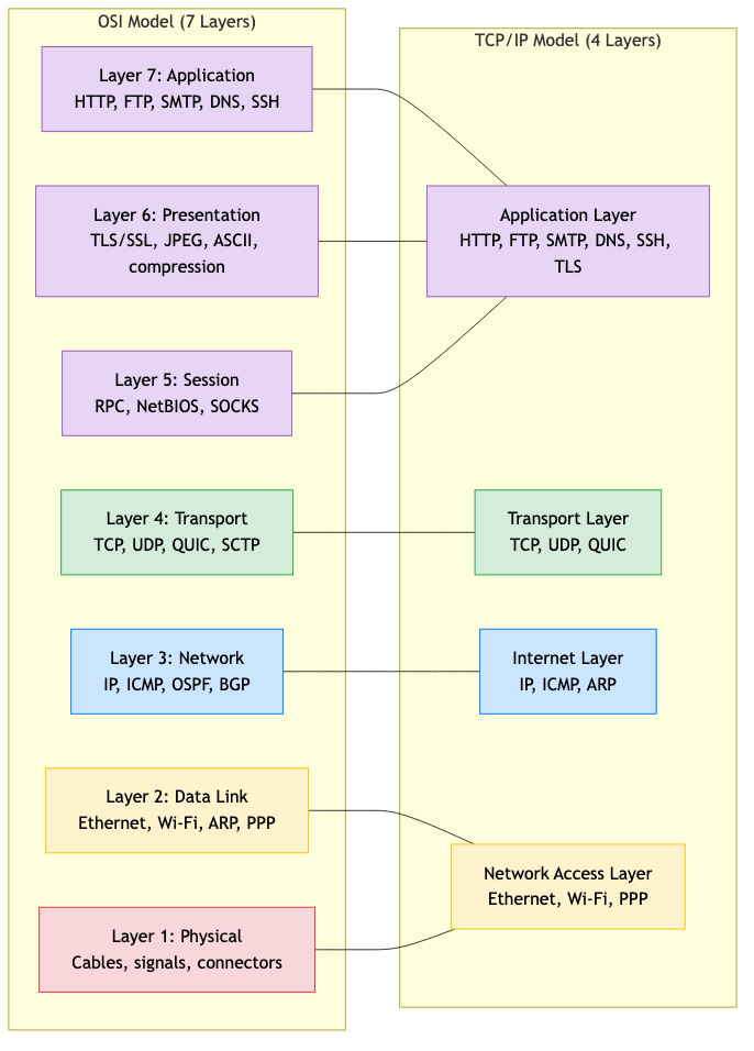
The Open Systems Interconnection model provides a conceptual framework for network communication.
Layer 7: Application    — HTTP, FTP, SMTP, DNS, SSH
Layer 6: Presentation   — Encryption/decryption, compression, encoding (TLS, JPEG, ASCII)
Layer 5: Session        — Session management, dialog control (RPC, NetBIOS)
Layer 4: Transport      — End-to-end delivery, reliability — TCP, UDP, QUIC
Layer 3: Network        — Routing, logical addressing — IP, ICMP, OSPF
Layer 2: Data Link      — Framing, MAC addressing, error detection — Ethernet, Wi-Fi
Layer 1: Physical       — Bits on the wire — cables, signals, connectors
Encapsulation
Each layer adds a header (and sometimes trailer) as data moves down the stack:
Application data
    ↓ + Application header
[Transport header | Application data]          → Segment
    ↓ + Network header
[Network header | Transport header | data]     → Packet
    ↓ + Data link header + trailer
[DL header | Network | Transport | data | DL trailer] → Frame
    ↓
Physical: bits on the wire
At the receiver, headers are stripped off as data moves up the stack (decapsulation).
Protocol Data Units (PDUs)
| Layer | PDU Name |
|---|---|
| Application | Message / Data |
| Transport | Segment (TCP) / Datagram (UDP) |
| Network | Packet |
| Data Link | Frame |
| Physical | Bit / Symbol |
TCP/IP Model (4 Layers)
The practical model used by the Internet. Maps roughly to the OSI model.
Layer 4: Application    — HTTP, DNS, SMTP, SSH (OSI 5-7 combined)
Layer 3: Transport      — TCP, UDP (OSI 4)
Layer 2: Internet       — IP, ICMP (OSI 3)
Layer 1: Link           — Ethernet, Wi-Fi (OSI 1-2 combined)
Why TCP/IP won: Simpler. Protocol-driven (designed to work, not just to model). The Internet runs on it.
Network Devices
Hub (Layer 1)
Repeater — copies incoming signal to all ports. No intelligence. Creates a single collision domain. Obsolete.
Switch (Layer 2)
Forwards frames based on MAC addresses. Learns which MAC is on which port (MAC address table). Creates separate collision domains per port.
Learning process: When a frame arrives on port X from MAC A → record "A is on port X." When a frame is destined for MAC B → look up B's port and forward only there. If unknown → flood to all ports (except source).
Spanning Tree Protocol (STP): Prevents loops in switched networks by disabling redundant links. Creates a loop-free tree topology.
Router (Layer 3)
Forwards packets based on IP addresses. Connects different networks (LAN to WAN, subnet to subnet). Maintains a routing table.
Makes forwarding decisions: Longest prefix match on destination IP. Each entry: destination network → next hop + interface.
Gateway
Translates between different protocols or networks. E.g., email gateway (SMTP ↔ X.400), IoT gateway (Zigbee ↔ IP).
Firewall
Filters traffic based on rules (source/destination IP, port, protocol, state). Can be a dedicated device or software on a router/host.
Types: Packet filter (L3/L4), stateful inspection (tracks connections), application-level gateway (proxy — inspects L7), next-generation firewall (NGFW — DPI, IPS, user identity).
Load Balancer
Distributes incoming requests across multiple servers.
Layer 4 (transport): Forward based on IP + port. Fast, simple. Layer 7 (application): Inspect HTTP headers, URL, cookies. Route based on content. Can do SSL termination, caching, compression.
Algorithms: Round-robin, least connections, weighted, IP hash, consistent hashing.
Key Networking Concepts
Circuit Switching vs Packet Switching
Circuit switching (telephone): Dedicated path established for the duration of the call. Resources reserved. Guaranteed bandwidth. Wastes resources when idle.
Packet switching (Internet): Data divided into packets. Each packet independently routed. Resources shared. Statistical multiplexing. More efficient but no guaranteed bandwidth.
Bandwidth, Throughput, and Latency
Bandwidth: Maximum data rate of a link (e.g., 1 Gbps).
Throughput: Actual data rate achieved (always ≤ bandwidth, reduced by overhead, congestion, errors).
Latency: Time for a packet to travel from source to destination.
Total latency = propagation + transmission + queuing + processing

Propagation: distance / speed_of_light_in_medium (~5 μs/km for fiber)
Transmission: packet_size / bandwidth
Queuing: time waiting in router buffers (variable)
Processing: time to examine header and make forwarding decision
Bandwidth-Delay Product
BDP = bandwidth × RTT
The amount of data "in flight" at any time. Important for window sizing in TCP.
Example: 1 Gbps link, 100 ms RTT → BDP = 12.5 MB. Need window ≥ 12.5 MB to fully utilize the link.
Store and Forward
A switch/router receives the entire frame/packet before forwarding. Adds latency (transmission delay at each hop) but enables error checking.
Cut-through switching: Start forwarding after reading the destination address (before receiving the full frame). Lower latency but can't check errors.
Internet Architecture
Edge and Core
Edge: End hosts (clients, servers) and access networks (home broadband, cellular, enterprise LAN).
Core: Backbone routers and high-speed links connecting ISPs. Packet switching at high speed.
ISP Hierarchy
Tier 1 ISPs (global backbone: AT&T, NTT, Lumen)
    ↕ peering / transit
Tier 2 ISPs (regional: Comcast, BT, Deutsche Telekom)
    ↕ transit
Tier 3 ISPs (local: small ISPs, campus networks)
    ↕
End users
Peering: Two ISPs agree to exchange traffic directly (usually free for similar-sized ISPs).
Transit: A smaller ISP pays a larger one for connectivity to the rest of the Internet.
Internet Exchange Points (IXPs): Physical locations where multiple ISPs connect and peer. Reduce latency and transit costs.
Standards Organizations
| Organization | Role |
|---|---|
| IETF (Internet Engineering Task Force) | Internet protocols (RFCs) |
| IEEE | LAN/WAN standards (802.3 Ethernet, 802.11 Wi-Fi) |
| ITU | Telecommunications standards |
| W3C | Web standards (HTML, CSS, WebSocket) |
| ICANN | Domain names, IP address allocation |
Applications in CS
- System design: Understanding networking enables designing scalable distributed systems (latency budgets, bandwidth planning, protocol selection).
- DevOps: Network configuration, firewall rules, load balancer setup, DNS management.
- Security: Network segmentation, firewall policies, intrusion detection, VPN configuration.
- Performance optimization: Understanding latency components, BDP, and protocol overhead enables tuning.
- Cloud architecture: VPC, subnets, security groups, load balancers, CDN — all networking concepts.