Combinational Circuits
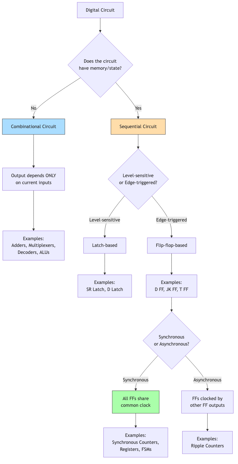
Combinational circuits produce outputs that depend only on current inputs (no memory/state). They are the building blocks of all digital computation.
Karnaugh Maps (K-Maps)
A visual method for simplifying Boolean functions for 2-6 variables.
2-Variable K-Map
        B
      0   1
A 0 | m₀ | m₁ |
  1 | m₂ | m₃ |
3-Variable K-Map
          BC
       00  01  11  10
A  0 | m₀  m₁  m₃  m₂ |
   1 | m₄  m₅  m₇  m₆ |
Note: Columns are in Gray code order (00, 01, 11, 10) so adjacent cells differ by one bit.
4-Variable K-Map
            CD
         00  01  11  10
AB  00 | m₀  m₁  m₃  m₂  |
    01 | m₄  m₅  m₇  m₆  |
    11 | m₁₂ m₁₃ m₁₅ m₁₄ |
    10 | m₈  m₉  m₁₁ m₁₀ |
Grouping Rules
- Group adjacent 1s in rectangles of size 1, 2, 4, 8, 16 (powers of 2).
- Groups can wrap around edges (left↔right, top↔bottom).
- Each 1 must be in at least one group.
- Maximize group size, minimize number of groups.
- Groups may overlap.
Each group of 2ᵏ cells eliminates k variables from the corresponding product term.
Example: 4-variable function f = Σm(0, 1, 2, 5, 6, 7, 8, 9, 10, 14):
            CD
         00  01  11  10
AB  00 | 1   1   0   1  |
    01 | 0   1   1   1  |
    11 | 0   0   0   1  |
    10 | 1   1   0   1  |
Groups: {m₀,m₁,m₈,m₉} → B'D', {m₂,m₆,m₁₀,m₁₄} → C'D, {m₅,m₇} → A'BD, etc.
Don't-Care Conditions
Some input combinations may never occur or the output doesn't matter. Mark as 'X' in the K-map. Can be treated as 0 or 1 to maximize group sizes.
Quine-McCluskey Algorithm
Systematic, tabular minimization. Handles any number of variables (unlike K-maps, which become impractical above 6).
Algorithm
-
Find all prime implicants: Group minterms by number of 1s. Combine adjacent groups that differ by one bit. Mark combined terms. Repeat until no more combinations.
-
Select minimum cover: Build a prime implicant chart. Find essential prime implicants (cover a minterm that no other PI covers). Use Petrick's method for remaining.
Computational complexity: Exponential in worst case (number of prime implicants can be exponential). For very large functions, use heuristic methods (ESPRESSO).
Standard Combinational Modules
Multiplexer (MUX)
Selects one of 2ⁿ inputs based on n select lines.
2:1 MUX: Y = S'·I₀ + S·I₁
I₀ ──┐
     │MUX──── Y
I₁ ──┘
      S
4:1 MUX: Y = S₁'S₀'·I₀ + S₁'S₀·I₁ + S₁S₀'·I₂ + S₁S₀·I₃
Universal function generator: Any n-variable function can be implemented with a 2ⁿ:1 MUX (connect function values to data inputs, variables to select lines). Or a 2ⁿ⁻¹:1 MUX by using one variable as a data input.
Demultiplexer (DEMUX)
Routes one input to one of 2ⁿ outputs based on select lines. The inverse of MUX.
Encoder
2ⁿ inputs (at most one active) → n-bit output code.
Priority encoder: Multiple inputs can be active; output is the code of the highest-priority active input plus a valid flag.
Decoder
n-bit input → 2ⁿ outputs (exactly one active).
Example: 3-to-8 decoder: Input 101 activates output Y₅.
Any Boolean function can be implemented as: decoder + OR gate (OR the outputs corresponding to minterms where f = 1).
Comparator
Compares two n-bit numbers A and B. Outputs: A > B, A = B, A < B.
1-bit comparator: Use XOR for inequality, XNOR for equality.
n-bit: Cascade from MSB to LSB, or use tree structure for speed.
Arithmetic Circuits
Half Adder
Adds two 1-bit numbers:
Sum = A ⊕ B
Carry = A · B
Full Adder
Adds two 1-bit numbers plus carry-in:
Sum = A ⊕ B ⊕ Cᵢₙ
Cₒᵤₜ = A·B + Cᵢₙ·(A ⊕ B)
Ripple-Carry Adder
Chain n full adders. Carry ripples from LSB to MSB.
Delay: O(n) — proportional to the number of bits. The carry must propagate through all stages.
Example: 4-bit ripple-carry adder:
FA₀: A₀,B₀,C₀ → S₀,C₁
FA₁: A₁,B₁,C₁ → S₁,C₂
FA₂: A₂,B₂,C₂ → S₂,C₃
FA₃: A₃,B₃,C₃ → S₃,C₄
Carry-Lookahead Adder (CLA)
Pre-computes carries in parallel using generate and propagate signals:
Gᵢ = Aᵢ · Bᵢ    (generate: produces carry regardless of input carry)
Pᵢ = Aᵢ ⊕ Bᵢ    (propagate: passes carry through)

C₁ = G₀ + P₀C₀
C₂ = G₁ + P₁G₀ + P₁P₀C₀
C₃ = G₂ + P₂G₁ + P₂P₁G₀ + P₂P₁P₀C₀
C₄ = ...
Delay: O(log n) using hierarchical CLA. Area: More gates than ripple-carry.
Subtractor
A - B = A + (-B) = A + (B' + 1).
Use an adder with B inverted and Cᵢₙ = 1. The same hardware does both add and subtract (controlled by a SUB signal that XORs each B bit).
ALU (Arithmetic Logic Unit)
Combines arithmetic (add, subtract) and logic (AND, OR, XOR) operations. Select lines choose the operation.
A simple ALU:
Operation select → MUX choosing between:
  00: A AND B
  01: A OR B
  10: A + B
  11: A - B
With flags: Zero (Z), Negative (N), Carry (C), Overflow (V).
ROM-Based Implementation
Any combinational function can be implemented with a ROM (Read-Only Memory):
- Address inputs = function inputs
- Data outputs = function outputs
- Each address stores the truth table row
For n inputs, m outputs: 2ⁿ × m ROM.
Advantages: Regular structure. Any function without redesign. Disadvantages: Size grows exponentially with inputs.
Programmable Logic Array (PLA): A more efficient alternative — programmable AND array + programmable OR array. Implements SOP form directly.
Hazards and Glitches
Static Hazard
A momentary wrong output when the correct output should remain constant.
Static-1 hazard: Output should stay 1 but briefly goes to 0. Static-0 hazard: Output should stay 0 but briefly goes to 1.
Detection: Look for adjacent 1s in the K-map that aren't covered by a single group. Adding a redundant group eliminates the hazard.
Dynamic Hazard
Output changes multiple times during a single transition. Occurs in multi-level circuits.
Elimination: Use a hazard-free two-level implementation, or add redundant terms.
In practice, hazards are usually acceptable in synchronous designs (outputs are sampled by flip-flops only at clock edges, after signals have settled).
Applications in CS
- Processor datapath: ALUs, multiplexers for data routing, decoders for instruction decoding.
- Address decoding: Memory-mapped I/O uses decoders to select devices.
- Priority encoding: Interrupt controllers use priority encoders.
- Lookup tables: FPGAs implement Boolean functions using LUTs (small ROMs).
- Error detection: Parity generators/checkers use XOR trees.
- Bus arbitration: Priority encoders and multiplexers manage shared buses.